GN 817.7

Types

  • Type D: Pneumatically double-acting, protrude / retract
  • Type A: Pneumatically single-acting, retract by spring force
  • Type E: Pneumatically single-acting, protrude by spring force

Coding

  • OP: Without position query
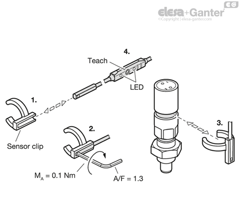
  • BS0,4: Position query on both sides, with plug, cable 0.4 m

Stainless steel AISI 303

Plunger pin surface hardened

Rod seal

Polyurethane PUR

Piston seal and O-ring

Acrylonitrile butadiene rubber (NBR)

Magnet

Neodymium, iron, boron (NdFeB)

Sensor

  • Housing

Polyamide (PA), black

  • Cable and plug

Outer sheath polyurethane (PUR), black

Sensor clip

Polyacetal (POM), black

Lock nut ISO 8675

Stainless steel, AISI 304

Stainless steel indexing plungers GN 817.7 with pneumatic operation can be easily and securely integrated into automated processes and can be positioned at locations where hand operation of the indexing plunger is not possible. Thanks to the material used, the indexing plungers are also suitable for more aggressive environments.

An integrated magnet allows the plunger pin position to be queried electronically by a sensor. The end limits (protruding and retracted position) are taught-in via the operating element on the sensor cable. They each send a high signal, which is indicated by the respective LED and can be processed by a machine control, for example.

The sensor electronics can also be accessed via IO-Link and offer the ability to set and read out the switching points and to block the teach button on the operating element. To avoid interference, no external magnetic fields should act on the indexing plunger. The pneumatic indexing plungers are supplied with a lock nut. With coding BS0,4, the sensor, sensor clip and an allen wrench are also supplied loose.

  • Range of indexing plungers 

  • Cable with Connector GN 330

  • IO-Link Device Description File 
  • Sensor Starting Operation 
  • IP Protection Classes 
  • ISO-Fundamental Tolerances 
  • Elastomer Characteristics 
  • Stainless Steel Characteristics 


The radial position of the sensor cable can be freely determined when installing the sensor clip.

Installation steps:

1. Insert the sensor into the sensor clip from the side.

2. Tighten the hexagon socket screw of the sensor.

3. Clip the sensor clip into the ring groove of the indexing plunger and then adjust the position by turning, if necessary.

4. During commissioning, teach the sensor to the end positions via the operating element or IO-Link in accordance with the operating instructions supplied with the sensor.

Pneumatic Properties
Operating pressure4 - 6 bar
Operating mediumFiltered, dried air, unoiled or oiled
Temperature range-20 °C ... +80 °C

Electrical Properties of the Sensor
Output function2x normally open (NO)____logo__817.7_SB-41850-0__
Output type2x PNP
Supply voltage12 - 30 V DC
Continuous current Ia≤ 100 mA
Connection type4-pole connector M8x1,____logo__817.7_SB-41852-0__
Plug (S)freely rotating with knurled screw connection
Protection typeIP 67-
Power consumption≤ 15 mA-
Voltage drop≤ 2.2 V-
Protection classIII-
Temperature range-20 °C ... +75 °C-
Shock and vibration resistance30 g, 11 ms / 10 ... 55 Hz, 1 mm-
EMVAccording to EN 60947-5-2-
Reverse polarity protectionYes-
Short-circuit protectionYes-
Activation impulse suppressionYes-
Communication interfaceIO-Link (V1.0)-
Cycle time 2.3 ms-
Process data length 2 bits-
Process data structure:-
Bit 0 = Switching signal Q1-
Bit 1 = Switching signal Q2-
Bit 2...7 = Empty-
Approvals, conformity declarations____logo__CE______logo__IO-Link__

LOOKING FOR SOMETHING:

Feeling overwhelmed with what product to choose?

Don’t delay, give OIC a call and talk to us about your industrial application. Our aim is to help your business choose the right Elesa+Ganter element for the function you need. Whether you need to clamp, close, connect, control, level, manoeuvre, measure or set. OIC has an Elesa+Ganter machine element to fit your need.

We want to find out about your industrial application need and where we can help. Our contact details are below.