DD51-E-RF

Electronic position indicators

Data transmission by radio frequency

DD51-E-RF

Electronic position indicators

DD51-E-RF

Electronic position indicators
Base and case

High-resistance polyamide based (PA) technopolymer.

Black base.

Case in the following colours:

  • C1: RAL 7021 grey-black, glossy finish.
  • C2: RAL 2004 orange, glossy finish.
  • C3: RAL 7035 grey, glossy finish.
  • C55: RAL 5005 blue, glossy finish.

Cover with perfectly sealed gasket and AISI 304 stainless steel UNI 6955 type self-tapping screws with six-lobe socket TORX®T06 (registered trademark by TEXTRON INC.).

The bonding between the base and the containment case using a high-performance sealant, in addition to preventing the penetration of dust and liquids, prevents them from detaching during use.

Boss

AISI 304 stainless steel with Ø 14 mm H7 reamed hole, fitting to shaft by means of AISI 304 stainless steel grub screw, hexagon socket and cup end UNI 5929-85, included in the supply.

Window

Transparent polyamide based (PA-T) technopolymer, moulded over the case and with a perfect seal. Resistant to solvents, oils, greases and other chemical agents (avoid contact with alcohol during cleaning operations).

Display

  • 5-digit LCD of 8 mm height and special characters.

The visualization parameters can be set and modified by the operator by means of appropriate keys:

  • values displayed in mm, inches or degrees
  • display of mode for use (absolute or incremental mode)
  • reading orientation (right or reverse).

Keyboard

Polyester membrane. Resistant to solvents, alcohol, acids, alkalis.

Internal gasket

O-ring front sealing in NBR synthetic rubber, between the case and the boss.

Brass bushing with double O-ring sealing in NBR synthetic rubber inside the rear cavity of the base (DD51-E-RF-SST-IP67).

Rear gasket

Foam polyethylene, supplied.

Standard executions

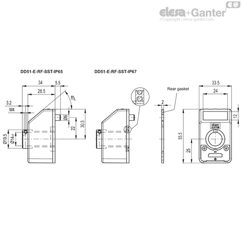
  • DD51-E-RF-SST-IP65: completely sealed indicator with IP 65 protection class, see EN 60529 table.
  • DD51-E-RF-SST-IP67: completely sealed indicator with IP 67 protection class, see EN 60529 table obtained by means of a brass bushing with double seal ring inside the rear cavity of the base.

Features and applications

DD51-E-RF position indicators, with battery power supply, can be used on passing through shafts in any position to provide the reading of the absolute or incremental positioning of a machine component.

The 5-digit display of 8,0 mm height ensures excellent readability even from a distance and from different viewing angles.

The window in transparent technopolymer protects the LCD display against accidental shocks.

The high protection degree, IP 65 or IP67, makes the indicator suitable for applications that require frequent washing, even with intense water jets.

The product is not suitable for use in continuous total or partial immersion.

In the operating mode, by using the 3 function keys, it is possible to select the incremental or the absolute mode, the unit of measure (mm, inches or degrees), reset the absolute counter or load a preset source value and the preset offset value.

In the programming mode, through the 3 function keys, it is possible to program the reading after one revolution of the shaft, the direction of rotation, the diplay orientation, the resolution (number of decimal digits displayed), the source value and the offset value, the max. speed of rotation and set the functions of the keys among different options available.

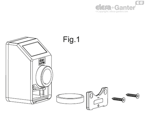
The internal battery has a battery life of 1.5 years. A specific symbol appears on the display when the battery needs replacing. It is easy to replace the battery by removing the front cover (Fig. 1) without having to remove the indicator from the drive shaft and without losing the configuration parameters.

Further technical information available in Operating instructions.


Quick positioning system

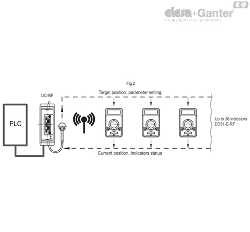
DD51-E-RF indicators (Elesa Patent) are networked to the control unit UC-RF via radio frequency (RF), constituting a wireless system for rapid positioning of the machine parts (fig.2).

The wireless connection allows:

  • reading of the current position
  • setting of the target position
  • configuration of all operational parameters

The radio frequency system network allows different machines to coexist in the same space without problems of mutual interference.

This system is particularly suitable for applications that require frequent format changes, facilitating the correct adjustment of the target/current position of the machine parts, also representing a safety system. In fact, even if a single DD51-E-RF indicator is not placed in the target position, PLC doesn’t allow the beginning of the machine production cycle, thus avoiding production issues.

The installation of the system is quick and easy as it does not require the use of connecting cables between the control unit and the indicators.

Further technical information available in Operating instructions.

 
Mechanical and electrical characteristics
Power supplyLithium battery CR2450 3.0 V
Battery lifeup to 1.5 years
Display5-digit LCD of 8 mm height and special characters
Reading scale-19999; 99999
Number of decimal digitsprogrammable (1)
Unit of measure

mm. inches, degrees

programmable (1)

Rotation max. speed

300/600/1000 r.p.m (2)

programmable (1)

Resolution10.000 impulses / revolution
Protection classIP65 or IP67
Working temperature0 ÷ 50 °C
Storing temperature-20 ÷ +60 °C
Relative humidityMax. 95% at 25°C without condensation
Conditions of useFor use in closed and sheltered places only
AltitudeUp to 2000 m
RF frequencies2400-2416MHz

(1) See the operating instructions.

(2) Default: 600 r.p.m.

Higher rotation speed to 600 r.p.m. can be maintained for short periods of time.

The maximum speed value, the number of drives and the frequency of transmissions affect battery life.

Battery life depends on the conditions of use (setup, temperature, ...). The indicated value is an estimate made in temperature conditions > 20 ° C and <30 °C, and default setup. Furthermore, this value refers to the condition of the device when it leaves the Elesa factory. Long storage times must always be considered for the estimation of the battery life when the device becomes operational.

Assembly instructions

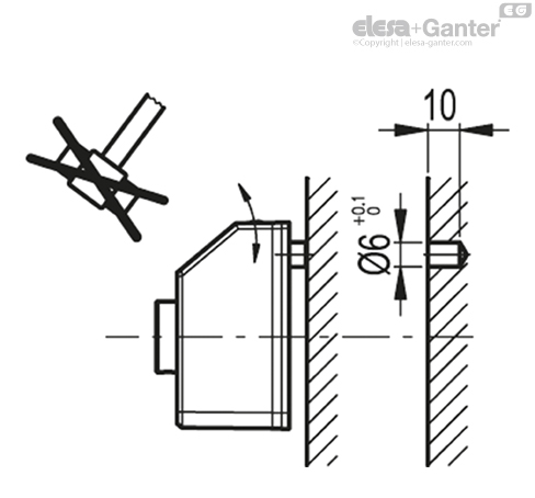
  • Drill a Ø 6 mm by 10 mm hole in the body of the machine with a 22 mm centre distance from the spindle to fit the rear referring pin.
  • Fit the indicator onto the spindle and make sure that the referring pin fit the hole.
  • Clamp the boss to the spindle by tightening the grub screw with hexagon socket and cup end, according to UNI 5929-85.
 

Accessories on request  (to be ordered separately)

  • MDX-51: polyamide based (PA) technopolymer knob.
  • RB51-SST: AISI 304 stainless steel reduction sleeves.
  • BSA51-E: die-cast zinc alloy bases for spindle locking, epoxy resin coating, black colour, matte finish. GN 302.1 adjustable handle with die-cast zinc alloy lever body and AISI 304 stainless steel clamping element. A Ø 6.1 mm hole to fit the referring pin of the indicator. Handle positioned either on the right or on the left. Fitting to the machine by means of two M4 cylindrical-head screws (not included in the supply).

Compatibility

The “-W2” electronic indicators are compatible exclusively with the electronic indicators and control unit of the same “-W2” version.

LOOKING FOR ALUMINIUM PROFILES:

Feeling overwhelmed with what product to choose?

Don’t delay, give OIC a call and talk to us about your industrial application. Our aim is to help your business choose the right Elesa+Ganter element for the function you need. Whether you need to clamp, close, connect, control, level, manoeuvre, measure or set. OIC has an Elesa+Ganter machine element to fit your need.

We want to find out about your industrial application need and where we can help. Our contact details are below.