GN 2410
Telescopic linear slides
with Runners Connected in Dual Configuration
GN 2410
Telescopic linear slides
Telescopic linear slides
GN 2410
Telescopic linear slides
Telescopic linear slides
Rail / Runner
Heat treatable steel
- zinc plated, blue passivated
- Raceways hardened
Balls
Anti-friction bearing steel, hardened
Ball cage
Steel, zinc plated
Rail Connection
Screw Steel, zinc plated
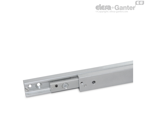
Telescopic linear slides GN 2410 consist of two linear motion ball slide rails connected at the runners. They are used, for example, in material handling or automation applications, or in jigmaking, to achieve a sliding motion in a linear direction when long extensions with low construction height of the rail are required.
The dual configuration has the advantage that both the radial and axial load capacities are identical. Meanwhile this design has proven less susceptible to dirt in practical use.
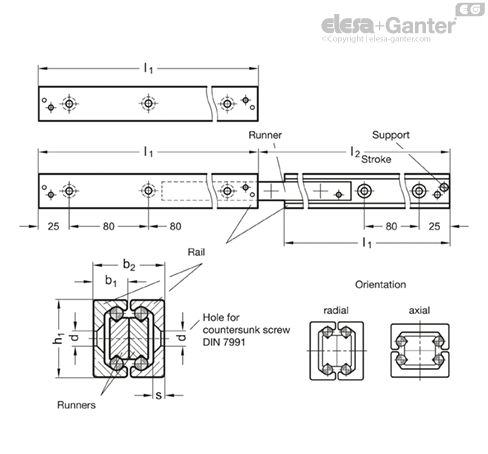
The rails and runner are equal in length. Both runners can be extended so that an extension is reached which is longer than the rail base length l1. Removing the support screws from the rails allows an extension of the rails on both sides.
External elements should limit the maximum sliding distance; the supports of the rail have been designed to guard against the inadvertent extraction of the runner from the rail.
- other lengths (based on the standard lengths grid dimension of 80 mm)
- Special lengths (bore, start and end distances)
Structure
All linear slides consist of an outer rail with a runner moving inside. Anti-friction bearings, kept at a distance and in position by means of a ball cage, lie between the rail and the runner. Rail and runner are made of heat treatable steel, enabling their use in industrial environments with higher requirements in terms of load rating, quiet operation and useful service life.
All designs are available in the nominal rail dimensions h1 = 28, 35 and 43 mm and may also be supplied beyond the standard range in lengths from 130 mm to 1970 mm, appropriate for individual requirements.
Linear slides are normally adjusted so that a clearance-free (i.e. moderately pre-stressed) match-up is created between rail and runner. The raceways of the rails and runners are induction hardened, which combined with the antifriction bearings results in lower wear and longer service life. Linear slides are permanently lubricated with a high-grade special grease designed for linear guide rail systems.
Depending on requirements, a variety of different types are available. Sliding distances of the runners are inside, partly outside or entirely outside the length of the rails. Fully extendable telescopic linear slides consist of linear slides directly interconnected at the rails, the runners or with the help of an intermediate profile.
To mount linear slides, countersinks in the rails and, depending on type of construction, threaded or countersunk holes in the runners are available. The compact style is generally advantageous for use in tight spaces.

Types
Telescopic linear slides, dual configuration, with full extension.


Assembly examples

Load rating of telescopic linear slides
in ascending order of the standard numbers
When selecting a suitable linear slide, it is primarily the available space, the desired stroke and the load carried which must be taken into consideration. The values listed below are intended as guidelines for selecting the most suitable nominal rail size.
The details on load rating are non-binding guide values given without liability and does not constitute any type of guarantee or warranty of its intended use. The user must determine in each individual case whether a product is suitable for the intended application. Environmental factors and aging may affect the stated values.

| Description | Load ratings |
| - | Co rad in N |
| GN 2410-28-210 | 444 |
| GN 2410-28-370 | 496 |
| GN 2410-28-450 | 405 |
| GN 2410-28-530 | 342 |
| GN 2410-35-370 | 534 |
| GN 2410-35-450 | 439 |
| GN 2410-35-530 | 403 |
| GN 2410-35-610 | 346 |
| GN 2410-43-450 | 1370 |
| GN 2410-43-610 | 1115 |
| GN 2410-43-770 | 870 |
| GN 2410-43-930 | 714 |
No details on the permissible load torques are given for the telescopic linear slides as these are normally used for paired applications. Loads of these dimensions occur to a minor degree because it may be assumed that the surrounding construction has sufficient rigidity and stiffness. Transferring load torques within certain limited is permitted.
Static load and deflection
The load values given in the tables refer to a maximum permissible force allowed to act in the middle of the fully extended profile rail at the third segment.
If the given values are observed and if the telescopic linear slide is fully extended, a minor deflection (sag) occurs at the end of the runner or of the rail. This has normally no detrimental effect on the proper function of the application. If required, guide values may be given if requested.
Mounting screws, assignment of the mounting holes
The standard mounting hardware is DIN 7991-10.9 countersunk head screws, to be mounted with the recommended tightening torque. Depending on type, not all mounting holes may be utilized. In general, these holes can be left unused. In exceptional cases, especially in bilateral stroke, mounting holes can be accessed by loosening the support screws and by pulling out the runner. The support screws are then put back in place.
Traversal speed, cage slip
The traversal speed in linear slides can be as much as 0.8 m/s. The particular application and the installation length can have an effect on this value. In the event of rapid changes of direction and high accelerating forces, cage slip may occur in some cases, especially in long ball cages. In cases such as these, the cage does not move synchronously with half the speed of the runner, but gradually loses its correct position owing to the slip. Whenever possible, running a blank stroke to the end of the traversal distance should be provided for back positioning.

LOOKING FOR ALUMINIUM PROFILES:
Feeling overwhelmed with what product to choose?
Don’t delay, give OIC a call and talk to us about your industrial application. Our aim is to help your business choose the right Elesa+Ganter element for the function you need. Whether you need to clamp, close, connect, control, level, manoeuvre, measure or set. OIC has an Elesa+Ganter machine element to fit your need.
We want to find out about your industrial application need and where we can help. Our contact details are below.