GN 1490

Linear guide rail systems

Steel / Stainless Steel, with interior travel path

GN 1490

Linear guide rail systems
Steel

GN 1490-NI

Linear guide rail systems
Stainless Steel

GN 1490

Linear guide rail systems
Steel

Type

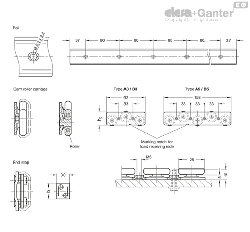
Type A3: with one cam roller carriage with 3 rollers

Type A5: with one cam roller carriage with 5 rollers

Type B3: with two cam roller carriages with 3 rollers

Type B5: with two cam roller carriages with 5 rollers

Identification no.

No. 0: without end stop

No. 1: with one end stop

No. 2: with two end stops

Guide rail

  • Steel ZB

Zinc plated, blue passivated

  • Stainless steel AISI 430 NI

Plain

Cam roller carriage

  • Base body

Stainless steel AISI 304

  • Roller

Ball-bearing, 2RS

Stainless steel AISI 440C

  • Roller bearing grease

FDA compliant, class H1

Permanent lubrication

End stop

  • Stainless steel AISI 304
  • Rubber stop (TPU), hardness ≈ 80 Shore A

Operating temperature -20 °C to 100 °C

Linear guide rail systems GN 1490 are generally installed in pairs, with a horizontal alignment, either vertically (as shown) or perpendicularly. They are used where simple, linear movements must be executed, such as in automation or in vehicle or machine engineering.

Optimal travel properties combined with low maintenance requirements can be achieved in connection with cam roller carriages matched to the guide rails without any play. The system is ready for use immediately after insertion of the cam roller carriages.

The linear guide rail systems consist of a guide rail, one or two cam roller carriages and the selected number of end stops. The parts are delivered unassembled. The guide rail can be installed on either the left or right side of the application. During installation of the cam roller carriages, the direction in which the load is received (marking notch) must be taken into account. The lubrication and maintenance instructions must be followed.

  • Other guide rail length (up to 3,994 mm)
  • Other hole spacing / finish

Mounting holes, fastening screws

During assembly, all mounting slots in the guide rail and the fastening thread on the cam roller carriage must be used. This ensures that the forces resulting from the maximum load FL / FA are reliably transferred to the surrounding structure. Failure to use fastening screws reduces the load capacity accordingly. Other production-related holes in the guide rails are not shown.

Various screws with M5 threads can be used for mounting the cam roller carriages. In contrast, the guide rail must be mounted with the screws listed in the table. It is generally recommended to use screws of strength class 8.8 in accordance with the specified tightening torque. The maximum torque for the accompanying countersunk screws of the end stops is 4-5 Nm, which results in the highest retaining force without deforming the guide rails.

The pre-installed rubber stops are automatically clamped by the countersunk screws and dampen the stops of the roller carriages at the respective end points.

Designation - standardInner slide
Hexagon socket countersunk head screw DIN 7991M 4 / M 5
Countersunk screw, Phillips DIN 965M 4 / M 5
Countersunk screw, Phillips DIN 7997Size 4.5 / 5

Lubrication and maintenance

The running surfaces of the guide rails must be lubricated with roller bearing grease before the first use. Possible lubricating greases include Cassida Grease GTX 2, Shell Gadus S2 V220 and Alvania EP 1 or Klüberplex BE 31-222. In food or pharmaceutical applications, FDA-compliant lubricating greases of class H1 or higher must be used as necessary. The grease should be distributed evenly over the entire length of the rail using a paintbrush.

After 50,000 cycles, the rails should be cleaned with a clean cloth and relubricated. If there is risk of soiling, the maintenance intervals should be shortened. In principle, however, soiling should be prevented with measures such as suitable covers or optimal positioning of the linear guide rail systems.

The following installation information should be taken into account in the design and assembly of linear guide rail systems.

This ensures smooth running, quiet operation, low wear, and proper function over prolonged use.

  • The mounting surfaces of the linear guide rail systems (guide rails and cam roller carriages) must be level, parallel, and at right angles as well as correctly situated relative to each other. If end stops are used, these must be positioned such that they are reached as simultaneously as possible.
  • Fastening holes should be applied in such a way that excludes twisting or warping of the guide rails during mounting. The specified mounting tolerance of +0.2 / +0.5 mm results in tensile loading of the rail in the direction of the application center, which ensures optimal and low-wear running.
  • After the linear guide rail systems are mounted, they must be checked to ensure smooth running. If something is wrong such as sticking or warping, the cause has to be determined and appropriately eliminated.
 

The maximum load capacity of the linear guide rail systems corresponds to two cam roller carriages with 5 rollers. If higher loads are to be moved with additional cam roller carriages, the functioning must be tested in a test setup. The total width as well as the stiffness of the application also play a role and can negatively impact the load capacity and wear properties.

To achieve the specified nominal load FR, the cam roller carriages must be installed such that the side with the larger number of rollers receives the load. To prevent mix-ups, this is marked with a notch on the base body of the carriage.

The total load FG of the application must be transmitted to the cam roller carriages as centrally as possible. Sudden impacts and jolts as well as strong vibrations acting on the linear guide rail systems are to be avoided. The application or absorption of torque forces in the MX and MZ directions via to the cam roller carriages is not intended.

 
h1FR per cam roller carriage in NMY per cam roller carriage in Nm
3 rollers5 rollers3 rollers5 rollers
29425650721
3780011501340

The maximum travel speed of the linear guide rail systems is 0.3 m/s. If end stops are used, the speed must be significantly reduced before reaching the stop to avoid damage. If large static or dynamic forces arise in the direction of travel, these must be absorbed by external stops since the end stops are not designed for this.

Linear guide rail systems are preferably installed vertically, in pairs, with a horizontal alignment. This results in the highest possible stability and torsional stiffness in the smallest installation space. The running properties are optimal in this arrangement, and wear is reduced to a minimum.

In contrast to telescopic slides, guide rollers can be used in a vertical orientation because no cage slip occurs since the design does not include a ball cage. It is only necessary to consider the direction in which the load acts so that the cam roller carriages can be inserted correctly into the guide rail.

The horizontal installation of the rail (lying down) is likewise possible with certain restrictions. The maximum load in this case is the nominal load FA. Due to the unfavorable rail cross-section, larger forces can be expected to widen the rail, which may lead to a collision between the cam roller carriages and the heads of the mounting screws. In case of doubt, check the function under load in a test set-up.

favorablevertically, on both sides
____logo__2492_MT-40785-0______logo__2492_MT-40787-0__
acceptablevertically shifted, on both sidesvertically inclined, on both sides
____logo__2492_MT-40789-0______logo__2492_MT-40791-0__
unfavorablevertically, on one sidehorizontally, on one side
____logo__2492_MT-40795-0______logo__2492_MT-40793-0__

  • For travel lengths exceeding the maximum standard length of the guide rails, multiple rails can be arranged in succession. In this case, the mounting holes for the guide rails must be positioned as precisely as possible to keep any possible offset between the guide rails to a minimum.
  • The guide rails can be cut to any length, if necessary. When sawing, care should be taken to not deform the profile cross-section. We recommend using a clamp. After cutting, the cut surfaces must be deburred and cleaned before lubricating the running surfaces.

LOOKING FOR ALUMINIUM PROFILES:

Feeling overwhelmed with what product to choose?

Don’t delay, give OIC a call and talk to us about your industrial application. Our aim is to help your business choose the right Elesa+Ganter element for the function you need. Whether you need to clamp, close, connect, control, level, manoeuvre, measure or set. OIC has an Elesa+Ganter machine element to fit your need.

We want to find out about your industrial application need and where we can help. Our contact details are below.