CFSW.
Hinges with built-in safety switch
SUPER-technopolymer
CFSW-C-A
Hinges with built-in safety switch
8 pole male connector, top axial output
CFSW-C-B
Hinges with built-in safety switch
8 pole male connector, back output
CFSW-C-C
Hinges with built-in safety switch
8 pole male connector, bottom axial output
CFSW-F-A
Hinges with built-in safety switch
8 pole cable, length 2.5 or 5 metres, back axial output
CFSW-F-B
Hinges with built-in safety switch
8 pole cable, length 2.5 or 5 metres, back output
CFSW-F-C
Hinges with built-in safety switch
8 pole cable, length 2.5 or 5 metres, bottom axial output
CFSW-FC-B
Hinges with built-in safety switch
0,2 m cable, 8 pole male connector, back output
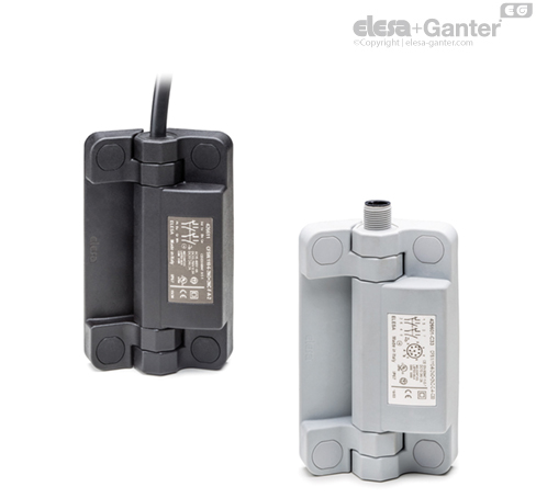
CFSW.
Hinges with built-in safety switch
Hinges with built-in safety switch
CFSW-C-A
Hinges with built-in safety switch
8 pole male connector, top axial output
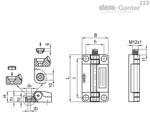
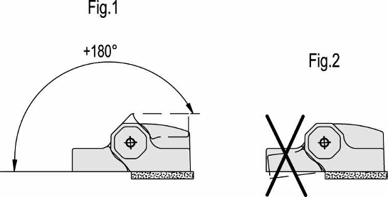


Material
- Hinge body: self-extinguish high-rigidity SUPER-technopolymer, black or grey colour RAL 7040 (C33).
- Rotation pin: glass-fibre reinforced polyamide-based tecnopolymer (PA), black or grey colour RAL 7040 (C33).
- Assembly kit (see assembly instructions):
- n°4 technopolymer covers (fig.3).
- n°4 technopolymer bushings (fig.4 and fig.5).
- n°2 thermoplastic elastomer safety plugs (fig.7) to guarantee IP67 protection class.
- Switch: four slow action electrical contacts with double interruption Zb shaped (see IEC EN 60947-5-1) wich can be set in normally open (NO) or normally closed (NC) mode in production.
Positive opening in compliance with IEC EN 60947-5-1 annex K: the separation of the electrical contacts is the direct result of an actuator action on which an action force is applied by means of non elastic elements, that is to say not dependant on, for example, spring-like elements.
The contact elements guarantee a self-cleaning action of the silver-alloy pastes.
Thanks to its housing made out of SUPER-technopolymer, the CFSW hinge guarantees the double insulation of the internal circuits, therefore there is no need of grounding connection. Furthermore, the housing protects the electric contacts from shocks, atmospheric agents and accidental penetration of tools.
Standard executions
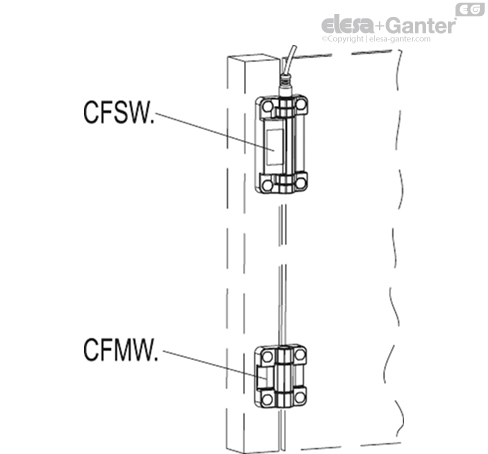
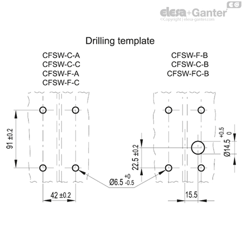
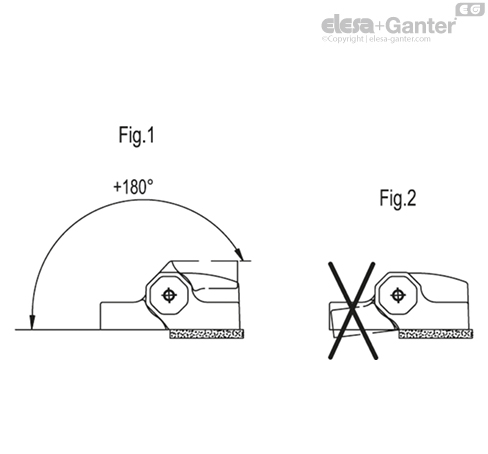
CFSW. hinge must be mounted with the side containing the microswitch on the fixed part (frame structure) and the other side on the movable part (door). The executions shown below refer to the hinges with the micro-switch on the right side.
- C-A: 8 pole male connector, top axial output.
- C-C: 8 pole male connector, bottom axial output.
- C-B: 8 pole male connector, back output.
- F-A: 8 pole cable, length 2 or 5 metres, back axial output.
- F-C: 8 pole cable, length 2 or 5 metres, bottom axial output.
- F-B: 8 pole cable, length 2 or 5 metres, back output.
- FC-B: 0,2 m cable, with 8 pole male connector, back output.
Cable type: UL/CSA STYLE 2587 8 X AWG 22.
Contact blocks in the standard execution:
- NO-NC-NO-NC: 2 NO contacts + 2 NC contacts.
- NO-NC-NC-NC: 1 NO contact + 3 NC contacts.

LOOKING FOR ALUMINIUM PROFILES:
Feeling overwhelmed with what product to choose?
Don’t delay, give OIC a call and talk to us about your industrial application. Our aim is to help your business choose the right Elesa+Ganter element for the function you need. Whether you need to clamp, close, connect, control, level, manoeuvre, measure or set. OIC has an Elesa+Ganter machine element to fit your need.
We want to find out about your industrial application need and where we can help. Our contact details are below.


